Noise diode control
To get noise adding radiometer modes working, the noise diode will need to be controlled by HIPSR. To do so, a “master” roach board will control the noise diode, using square wave generator gateware tied to the GPIO output on the ROACH board.
The sections that follow give more detail into how this is/will be achieved.
Firmware overview
While the firmware is still in development, here’s the general idea:
- Sync all boards up using the 1PPS and some sync pulse logic.
- Generate a square wave to control the noise diode
- Take the ADC data, do a small FFT and take the power.
- Demux the FFT data into ON and OFF. This is controlled by the square wave generator.
- Accumulate the ON and OFF spectra
- Store the sum ON-OFF for each channel in a shared BRAM.
Note that while only one board controls the noise diode, all boards require square wave generators. The other option would be to distribute the square wave between boards with cables; this would be pretty horrible.
Square wave generation
Firstly, we need to generate the signal with which to control the noise diode. This is done with the sq_wave_gen block:
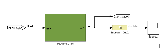
The sq_wave_gen block generates a boolean signal which cycles between ON (True), and OFF (False).
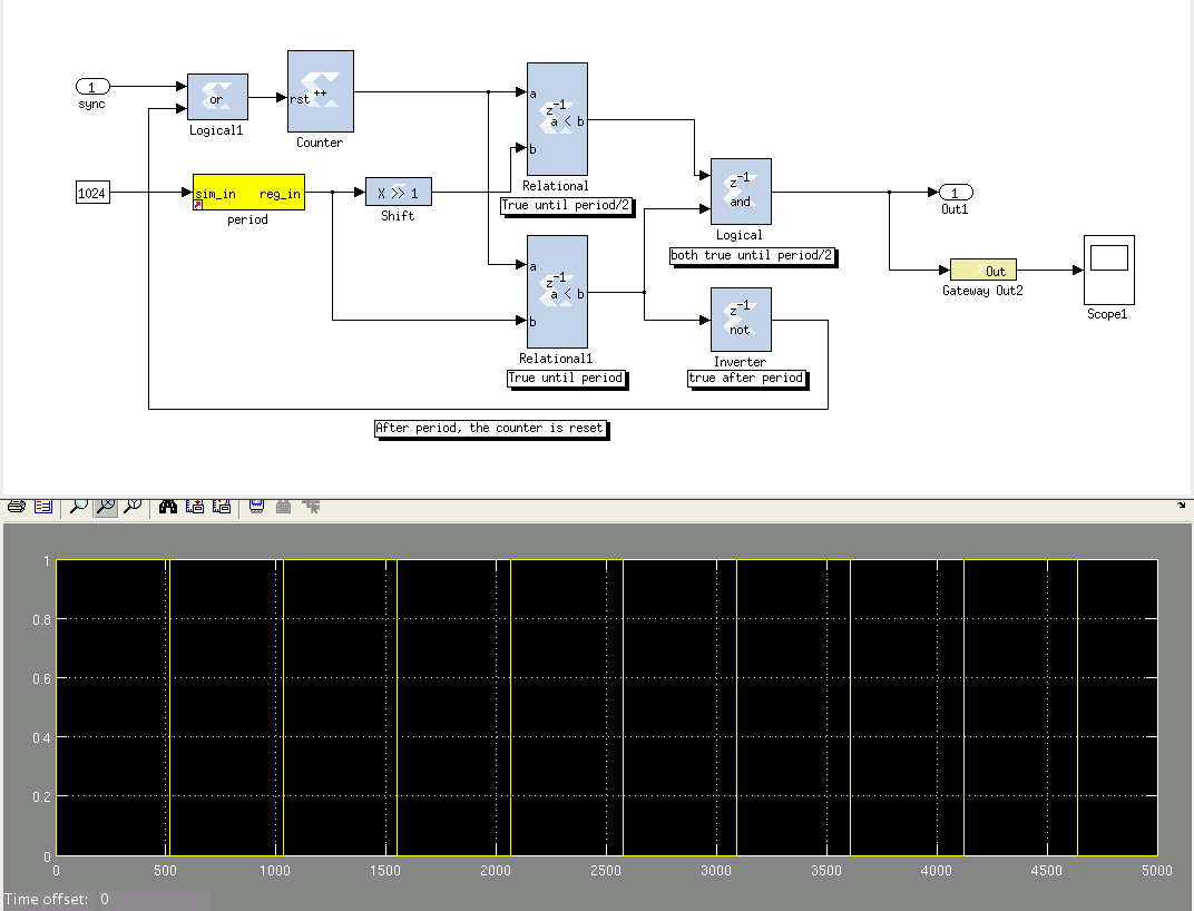
The logic inside the sq_wave_gen block, and a simulated square wave. This produces a boolean square wave signal of the given period. The period can be controlled by the period register.
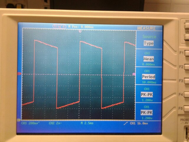
The resulting square wave, as measured on an oscilloscope in the lab. The output of sq_wave_gen is tied to the GPIO headers. These can run at up to 10 MHz, and output a 3.3V level signal.
FFT and power
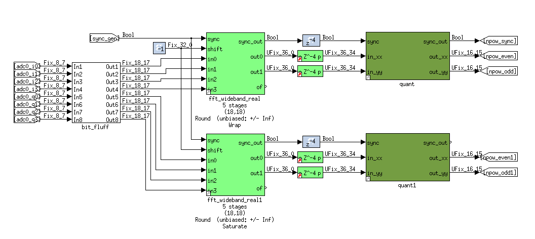
The output of the ADC is changed from 8_7 bits to 18_17 bits, then FFT’d. There are 16 complex channels output. The power (autocorrelation) is taken, then the signal is quantized down to 8 bits, in prep for the vector accumulator.
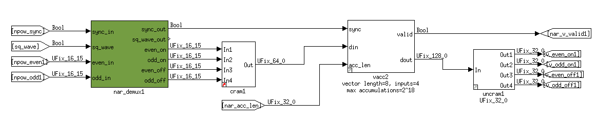
Demux and accumulation
The output of the FFT needs to be separated into ON and OFF, which corresponds to the noise diode being on and off. To do this, the square wave generator is used as an input to a ‘demux’ block.
After separating the two signals, they are fed into vector accumulators. As the vectors are short (2x8 channels), bits grow quickly. As such, the input is 8 bit, and the output is 32 bit. This gives 2^24 max accumulations before bit overflows can occur (might need to increase this).
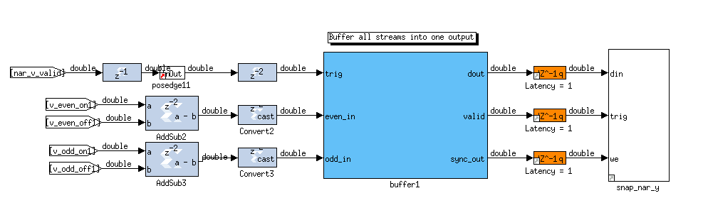
Data readout
To compute the sum ON - OFF, the outputs of the vector accumulators are fed into an adder block (which is set to minus). This creates a 33 bit signed number (can be -ve), which is recast to 32.
After this, the signal is buffered and then fed into a shared BRAM, which can be accessed via the ROACH’s Power PC.
Testing
TODO.